MHU 115
Analogue addressable Control and Indicating Equipment
The analogue addressable Control and Indicating Equipment with module structure with capacity up to 256 elements.
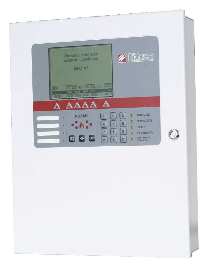
The analogue addressable Control and Indicating Equipment with module structure with capacity up to 256 elements. The C.I.E. can be completed with communication module SL-RS485 allowing connection of repeater, units of outputs, input/output devices, OPPO and ZDP. For networking up to sixteen C.I.E. and repeaters on insulated lines communication module RS485/422 can be added to the C.I.E.
- Modular structure
- The graphical display with backlight clearly showing system status
- Structured menu for easy operation with six multifunctional keys
- Structured memory for over 1000 system events
- Possibility of connecting of printer
- Connection of PC via USB or serial port
- Configuration and diagnostic of system from PC
- Actualization of firmware of C.I.E. with help of PC
- Compatibility with existing detectors and elements of systems LITES
The modular structure provides:
- 2 position for the line or loop module with the ability to connect up to 256 devices
- 1 position for the communication module on simple or circle line SL-RS 485 enabling to connect up to 16 devices
- 1 position for the communication module on isolated simple or circle line RS 485/422 enabling to connect mutual up to 16 C.I.E. and repeaters
- 3 programmable inputs
- 6 programmable outputs
| Line module | |
|---|---|
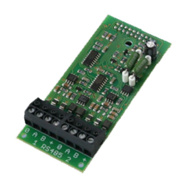 | Module of one circle line with capacity of 128 addresses for connection of interactive detectors and addressable elements |
| Circle line is possible to divide on two simple lines | |
| C.I.E. can be equipped with two line modules | |
| Loop module | |
|---|---|
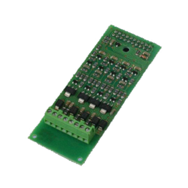 | Module for connection of conventional detectors |
| Four conventional loops | |
| Connection of up to 25 detectors on loop | |
| C.I.E. can be equipped with two loop modules | |
| Communication module SL-RS 485 | |
|---|---|
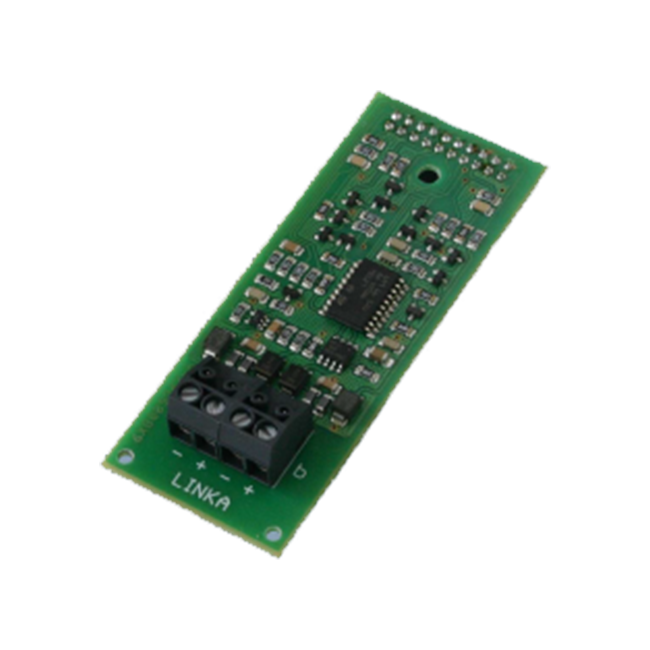 | Repeater MHS 815 |
| Units of outputs MHY 918 | |
| Input/output devices MHY 925 | |
| OPPO - MHY 919 | |
| ZDP | |
| Communication module RS 485/422 | |
|---|---|
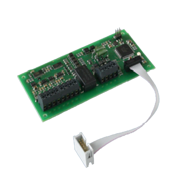 | It serves to networking of C.I.E. MHU 115 and repeaters MHS815 on circle or simple isolated leading ofcommunication line RS 485/422. |
| Technical parameters | |
|---|---|
| Power supply | 230V+10%-15% / 50 Hz ± 5% |
| Power consumption | max. 75 VA |
| Standby accumulator supply | |
| Inside of C.I.E. | 2 × 12 V / 12Ah |
| Outside of C.I.E. | 2 × 12 V / 38 Ah |
| Number of line/ loop modules | 1 or 2 |
| Line module: | |
| Wiring and leading of lines | circle (distributable on simple), two-wire, branch able |
| Number of addresses C.I.E./line | 256/128 |
| Types of connectable elements | addressable and analogue detectors and elements of system LITES |
| Loop module: | |
| Wiring of loops | balanced loop |
| Number of addresses C.I.E./module | 8/4 |
| Number of elements per loop | max. 25 |
| Types of connectable elements | conventional detectors of system LITES |
| Line resistance line/loop | max. 100 Ω |
| Inputs opto-isolated | 3 × 9 ÷30 V |
| Outputs watched open collector | 6 × max. 30 V, 0,15 A |
| Communication channels: | |
| SL-RS 485 | line for connection of elements with given configuration |
| RS 485/422 | isolated line for networking of C.I.E. |
| RS 232 | for connection of serial printer or configuration PC |
| USB | for connection of configuration PC |
| Output voltage | 24V |
| Allowed quiescent consumption | |
| By operation from mains | max. mA |
| By operation from ACU (24 hrs.) | 2 × 12 Ah max. mA, 2 × 36 Ah max. mA |
| Allowed alarm consumption | max. mA |
| IP rating according to ČSN EN 60529 | IP 30 |
| Safety class equipment according to ČSN EN 60950 | I |
| Radio screening degree according to ČSN EN 55022 | B-class equipment |
| Dimensions | (332 × 420 × 108) mm |
| Weight (without standby source) | cca 6 kg |
Configuration and diagnostic program
The system allows a very wide range of programming, that are defined in the configuration program on the PC, and with help of USB or serial interface are recorded to the C.I.E. The configuration program is used to assign the user text to individual addresses of system, parameterization of interactive detectors, creating of individual groups of detectors and defining of their properties. Also serve to define the properties and relationships in the system, such as the conditions for activation of the individual outputs, activation of user bi-color LED, a way of signaling by the activation of input, etc. It is also used for system diagnostics and firmware update of C.I.E.
| Working conditions | |
|---|---|
| The equipment is intended for the interior of objects without occurrence of aggressive substances, and for places where its protection and climatic immunity conform, and where sudden temperature changes leading to dew and ice accretion don’t occur. | |
| Working temperature range | -25 °C to +70 °C |
| Relative humidity | ≤ 75%, 10 days 10 days in a year 95%, on other days occasionally 85% |
| Atmospheric pressure | (86 ÷ 106) kPa |
| Mounting position | vertical on walls without vibrations |